Wednesday, December 22, 2010

Two steps forward, then subtract one

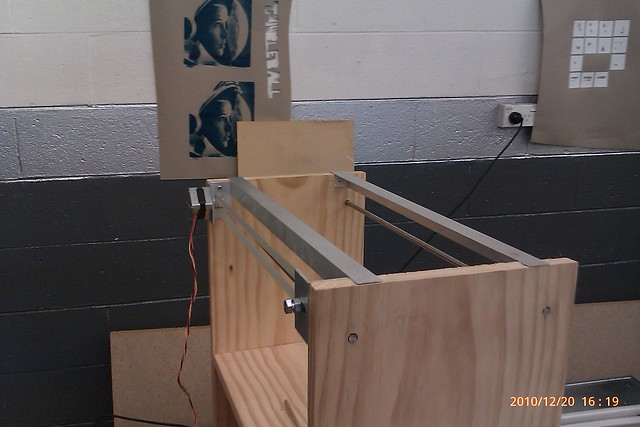
Well first off I made a mileston on Tuesday night at Tangleball, I fitted the stainless steel rods and mounted the cross beab attaching both linear bearings, plus came up with a novel apprach to afixing the belt to the bearing, more on that later.

IMAG0101

Above is when I mounted the rods, and below is when I attached the belt to the linear bearing.
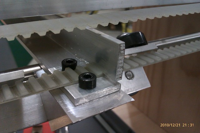
IMAG0102

Did you notice how I did it?

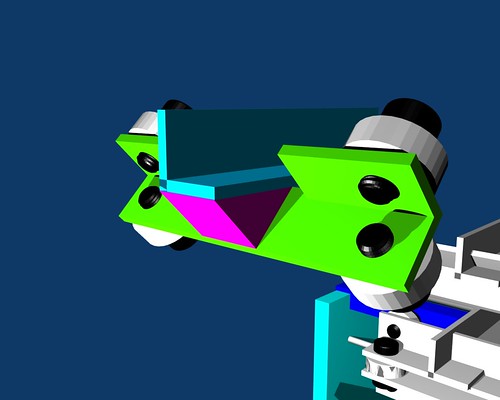
Here is the cross beam
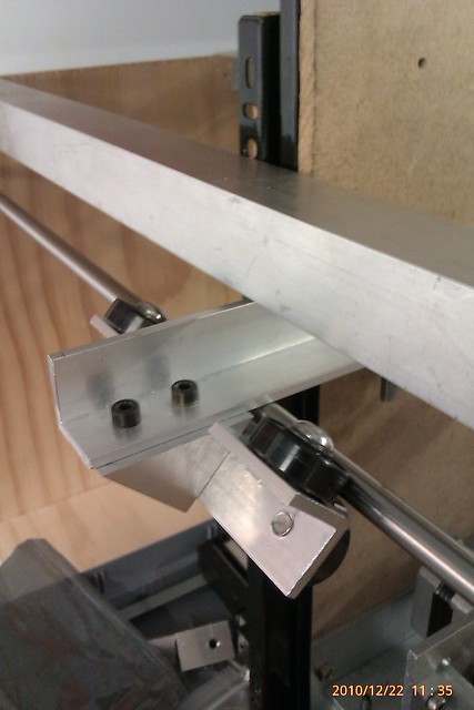
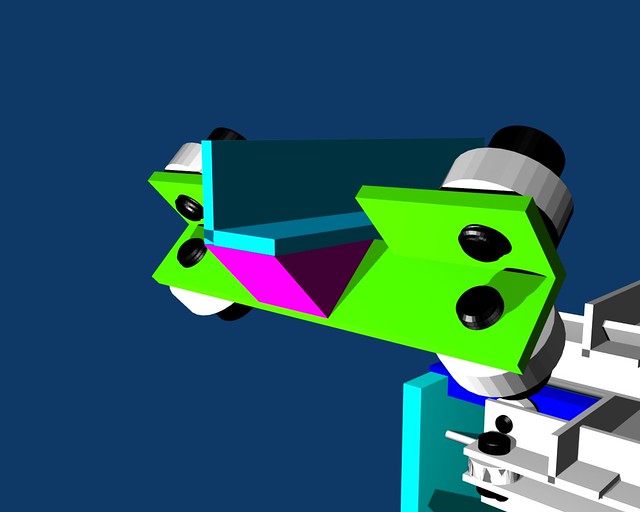
IMAG0105

Compared to my sketch in Blender.
0001

That was last night, and it was a hot night too, and I left Tangleball late, so I left the 3D printer in my car. What I did not think about was that I also had to go to the mall after work to do my meager Christmas shopping, as I had to get some bits for my friends' Christmas present which I will drop off tomorrow night, yay, another 2 hour drive there and 2 hour drive back, hope she will like it all the same.

IMAG0106

Anywho, back on track, I had to leave my 3D printer at work to save it from being damaged or stolen while I went shopping.
I'm not popular with my boss about doing that, because people are gandering over it, trying to make sense of cocaphoney. Though I did iinvite one guy over to give some feedback, but moments before he did, I peered at it as I was heading from the bathroom, and I noticed something, something real bad.

The rods sag under the weight of the Z axis, greeeat, just what I need!

This is on top of the Y axis needing an extra 608 bearing, larger holes for the other linear bearing so that there is slack enogh to attach springs from one side to the other to pull both linear bearings into full contact with the rod.
Sorry no pic or video because the sag is so timy that the camera won't pick it up, but its a sag of 2mm.

When the guy came over, he suggested making L brackets to mount more 608 bearings on the top aluminium L angle, to offset the weight of the Z axis off the rod.

On all the other ideas, this one is the most doable, and I cam make it with some of the tools I will have available outside of work over Christmas, damn Christmas, ah well can't complain too much, as I need the rest.

current way of making this L bracket, which I will work on sketching up tonight, again, sorry, no photo, is a length of flat aluminium with holes at strategic locations, then bending it in a vice, obiously the 608 bearing will need to be in mounted in a slot for the screw to pass through and the whole thing to move up and down, though I feel I will need more 608 bushings, and if I want any more of those to be made up, then this Friday is my last chance before Christmas.
Once that has been done, I will need to attach yet more springs to equalize the load pressure off the rods.

I still need to mount the Z axis to the bracket and constrain t down with a bearing also, either one of the spare 625 bearings or a 608 bearing, again i've not thought this out completely so it will have to done on the fly.

Saturday, December 18, 2010

Y is it taking so long?

So I wanted to give an update to my 3D printer.
Last time I said I wanted to have the Y axis completed this week, which may not happen as I have set time aside to do Christmas cards, so the intial plan of of heading down to Tangeball, and drilling holes for the stainless steel rod into the wood and making the cross beam will have to wait till next week, Tuesday night.


Here is most of the parts except the cross beam and the other stainless rod, which is cut to the same length.


It may not seem like much, but to redesign the the linear bearing in such a way it's under engineered to allow for my many mistakes.
Still plan to use 608 bearings with a busing inside so that I can use an M6 screw, the reason for using an M6 screw is that the thread pitch is enough to support the weight of the Y and Z axis  withouth worry of  thread stripping, as if I had used 8mm thread in the 3mm wall L bracket, it would just have 1 and a bit turnes in the thread, with 6 mm I have 3 turns of thread in the 3mm wall L bracket.

I took the oppotunity to do a short video explaining my crazy ideas, I can't help it, I love making robots, this project is no exception.


So i'll mount most of this this weekend, and glue on the pulley to the motor with LocTite 680 at work on Monday, and drill holes on Tuesday night.

Then it will be onto establishing the hight of the extruder to the bed, personal time frame to do that is mid to late next week.

I'm also going to have to take the half day from work on Friday to take up to my friend in Whanagarei her Christmas present.

Wednesday, December 8, 2010

Is newer better?

Well I decided to download and try out the latest and greatest host software and firmware.

I set forth to do the normal changes, but couldn't for the life of me figure out why the host would crash each time I wanted to jog an axis.  It was rather stupid of me, I cleaned the 5D gecode -> Interpreter and reinstalled the files, again, and again.  Finally after posting on the forum, I tried something else out, delete the applet directory, as this is where a fresh compile of the code goes.

Presto!


It worked, powered up the machine, then the host software.  Doing it this way instead of the other way around which I had been doing just fine for the old firmware worked.  I hate to think wat will happen when I use the bluetooth at the end of the build cycle, as I did have it going before quite reliably.

I also upgraded my Java version, I hadn't done it because of frequent host crashes, however another recent post suggested editing the repRap.bat and change "Java" to "C:\Program files\Java\bin\java.exe" or where ever it is located.

That fixed that long outstanding issue.

Still have to restart my computer after exiting from a crash or even a normal exit.
It is still unknown if this is a problem with Java, or its implementation in the host, my feeling its the host, but what I just don't know.

Lastly I found that with the atest firmware it wants to home too quickly for my flatbed scanner, this I believe is due to the acceleration in the firmware, sadly because it is desgned for equal stepper motors all round, which I don't, I want this turned off anyways, which I have done now in the firmware configuration file.


Forwards and nwards to the next problem, redesigning the Y axis, as folding the internal flap didn't work out, I did this at work when I wasn't even thinking, I was just too tired and not with it.

0001

Which was ok, as I had to wait about 15 minutes between charge cycles when fixing units anyway, which had charging faults.

Using this method for the Y axis, adds strength and alows for an easy way to attach a bar so that it can reach an endstop if I need to, plus affixing the belt onto it as well.
http://forums.reprap.org/read.php?12,59159