Wednesday, December 22, 2010

Two steps forward, then subtract one

Well first off I made a mileston on Tuesday night at Tangleball, I fitted the stainless steel rods and mounted the cross beab attaching both linear bearings, plus came up with a novel apprach to afixing the belt to the bearing, more on that later.

IMAG0101

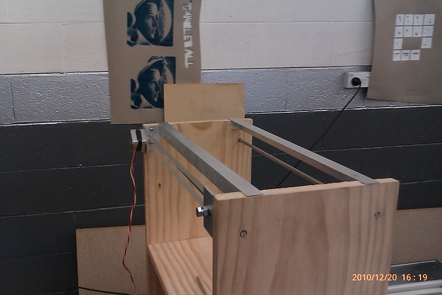
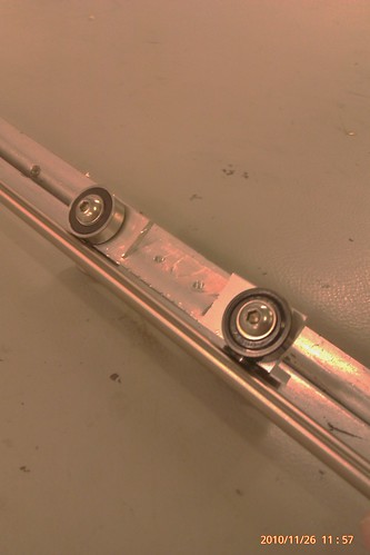
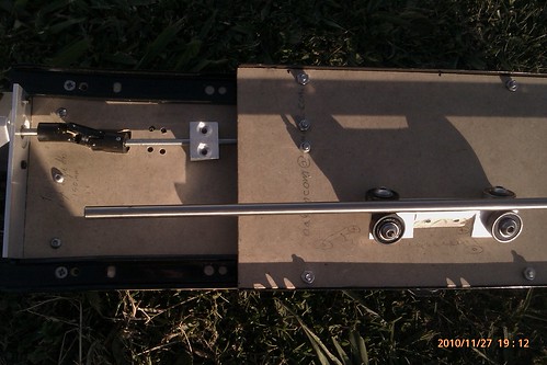
Above is when I mounted the rods, and below is when I attached the belt to the linear bearing.

IMAG0102

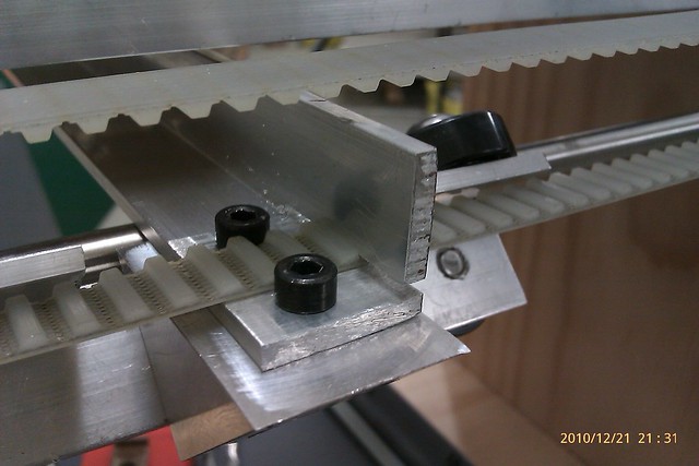
Did you notice how I did it?

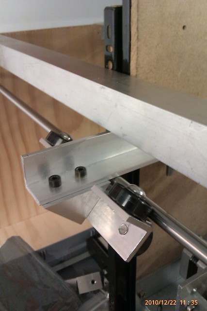
Here is the cross beam
IMAG0105

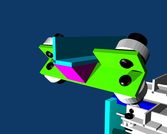
Compared to my sketch in Blender.
0001

That was last night, and it was a hot night too, and I left Tangleball late, so I left the 3D printer in my car. What I did not think about was that I also had to go to the mall after work to do my meager Christmas shopping, as I had to get some bits for my friends' Christmas present which I will drop off tomorrow night, yay, another 2 hour drive there and 2 hour drive back, hope she will like it all the same.

IMAG0106

Anywho, back on track, I had to leave my 3D printer at work to save it from being damaged or stolen while I went shopping.
I'm not popular with my boss about doing that, because people are gandering over it, trying to make sense of cocaphoney. Though I did iinvite one guy over to give some feedback, but moments before he did, I peered at it as I was heading from the bathroom, and I noticed something, something real bad.

The rods sag under the weight of the Z axis, greeeat, just what I need!

This is on top of the Y axis needing an extra 608 bearing, larger holes for the other linear bearing so that there is slack enogh to attach springs from one side to the other to pull both linear bearings into full contact with the rod.
Sorry no pic or video because the sag is so timy that the camera won't pick it up, but its a sag of 2mm.

When the guy came over, he suggested making L brackets to mount more 608 bearings on the top aluminium L angle, to offset the weight of the Z axis off the rod.

On all the other ideas, this one is the most doable, and I cam make it with some of the tools I will have available outside of work over Christmas, damn Christmas, ah well can't complain too much, as I need the rest.

current way of making this L bracket, which I will work on sketching up tonight, again, sorry, no photo, is a length of flat aluminium with holes at strategic locations, then bending it in a vice, obiously the 608 bearing will need to be in mounted in a slot for the screw to pass through and the whole thing to move up and down, though I feel I will need more 608 bushings, and if I want any more of those to be made up, then this Friday is my last chance before Christmas.
Once that has been done, I will need to attach yet more springs to equalize the load pressure off the rods.

I still need to mount the Z axis to the bracket and constrain t down with a bearing also, either one of the spare 625 bearings or a 608 bearing, again i've not thought this out completely so it will have to done on the fly.

Saturday, December 18, 2010

Y is it taking so long?

So I wanted to give an update to my 3D printer.
Last time I said I wanted to have the Y axis completed this week, which may not happen as I have set time aside to do Christmas cards, so the intial plan of of heading down to Tangeball, and drilling holes for the stainless steel rod into the wood and making the cross beam will have to wait till next week, Tuesday night.


Here is most of the parts except the cross beam and the other stainless rod, which is cut to the same length.


It may not seem like much, but to redesign the the linear bearing in such a way it's under engineered to allow for my many mistakes.
Still plan to use 608 bearings with a busing inside so that I can use an M6 screw, the reason for using an M6 screw is that the thread pitch is enough to support the weight of the Y and Z axis  withouth worry of  thread stripping, as if I had used 8mm thread in the 3mm wall L bracket, it would just have 1 and a bit turnes in the thread, with 6 mm I have 3 turns of thread in the 3mm wall L bracket.

I took the oppotunity to do a short video explaining my crazy ideas, I can't help it, I love making robots, this project is no exception.


So i'll mount most of this this weekend, and glue on the pulley to the motor with LocTite 680 at work on Monday, and drill holes on Tuesday night.

Then it will be onto establishing the hight of the extruder to the bed, personal time frame to do that is mid to late next week.

I'm also going to have to take the half day from work on Friday to take up to my friend in Whanagarei her Christmas present.

Wednesday, December 8, 2010

Is newer better?

Well I decided to download and try out the latest and greatest host software and firmware.

I set forth to do the normal changes, but couldn't for the life of me figure out why the host would crash each time I wanted to jog an axis.  It was rather stupid of me, I cleaned the 5D gecode -> Interpreter and reinstalled the files, again, and again.  Finally after posting on the forum, I tried something else out, delete the applet directory, as this is where a fresh compile of the code goes.

Presto!


It worked, powered up the machine, then the host software.  Doing it this way instead of the other way around which I had been doing just fine for the old firmware worked.  I hate to think wat will happen when I use the bluetooth at the end of the build cycle, as I did have it going before quite reliably.

I also upgraded my Java version, I hadn't done it because of frequent host crashes, however another recent post suggested editing the repRap.bat and change "Java" to "C:\Program files\Java\bin\java.exe" or where ever it is located.

That fixed that long outstanding issue.

Still have to restart my computer after exiting from a crash or even a normal exit.
It is still unknown if this is a problem with Java, or its implementation in the host, my feeling its the host, but what I just don't know.

Lastly I found that with the atest firmware it wants to home too quickly for my flatbed scanner, this I believe is due to the acceleration in the firmware, sadly because it is desgned for equal stepper motors all round, which I don't, I want this turned off anyways, which I have done now in the firmware configuration file.


Forwards and nwards to the next problem, redesigning the Y axis, as folding the internal flap didn't work out, I did this at work when I wasn't even thinking, I was just too tired and not with it.

0001

Which was ok, as I had to wait about 15 minutes between charge cycles when fixing units anyway, which had charging faults.

Using this method for the Y axis, adds strength and alows for an easy way to attach a bar so that it can reach an endstop if I need to, plus affixing the belt onto it as well.
http://forums.reprap.org/read.php?12,59159

Tuesday, November 30, 2010

Been too busy to blog

Although I haven't said anything for a while, its not to say i've been idle, rather the opposite, between real life, work, a robotics competition etc, i've only just got back into it again.


So I mounted the partly built Z axis, and found a major issue, forcing a redesign of this.


So I sketched up an idea, using 608 bearings
Y-Constrained-idea-1

And made a mockup of it.
IMAG0053

Then I went back to working on finishing the Z axis.  I made up two blocks, 1 threaded drive block, the other a guide block, and no matter what I did, I got binding, so I am still working on this, even today.
The photo shows the severe misalignment contributing to the bidinding issue, also I have to get new blocks made.

To the right of the photo is another view of the mockup of the linear bearing for the Y axis, working on this at the same time as the Z, and using the suggestions people have made, I am now making  them.

IMAG0054

I am still not happy with the bending I had done in the mockup, so before I do this for real, I reckon aother test is in order.

Sunday, July 18, 2010

Tweaking the extruder

Interesting developments this week, managed to get the extruder to extrude PLA at a consistant rate without stalling, but only through the host test extrude, still this is big step forwards.

I've also begun work on redoing the Z axis.

Before I get too far there is still one little thing that needs doing, setting the value of the extrusion rate in firmware for the motherboard, E_STEPS_PER_MM.
For the standard Mendel with a splined shaft this value is 0.706, while Adrian B. has set this to 2.0 for his geared extruder, though I found out last night that this number is wrong, its too low.
First I had read this blog post
http://www.brokentoaster.com/blog/?p=358

After which I had to ask Adrian if this is equation he used, which it isn't, instead Adrian says that its

1 / (PI . Dpw / Stepper steps) x ((ratio of filament in to nozle dia or Fd / Nd)squared)


If 
PI = 3.14159265
Dpw = 5mm
Stepper steps = 400
Fd = 3mm
Nd = 0.5mm
Comes to 0.707 which is wrong, so I fiddled the equation a bit to come to


((PI x Dpw / Stepper steps) x ((ratio of filament in to nozle dia or Fd / Nd)squared)) / 2

I get 0.706858, and the note in the firmware says its emperically adjusted, so by taking 3sf past the dp you get 0.706.

I don't know how correct this is yet, so i'll update the wiki later

Sunday, June 27, 2010

Some Progress on the extruder

After more than 50 iterations on my "JunkStruder" as I like to call it, a major delay in acquiring fibreglass coated Nichrome to overcome the intense heat needed to extrude PLA, ~275 degrees Celsius seems to be working, but not by the stepper yet.

I did have a big problem that I was very happy in my decision to use a BakeLite thermal break was a good one.
Essentially I broken the filament right at the top of the thermal break, gah!  But when I applied a butane torch flame, yeah that's right a butane torch right on the thermal break, I stuck down a piece of filament so that it welded together, then just turned on the extsruder heater to remove the stuck filament.

Thanks to Paul Marson, a mate of mine who suggested using a pot handle, turned on an a lathe to produce a thermal break, any other plastic like PTFE or PEEK would have melted.

On Friday night, cause I really don't know how to use a lathe, yet, Paul turned out a piece of stainless steel tube that I got from the hobby shop a couple days before, 1/4 inch OD 0.049 wall, OD turned down to 6.0mm and ID drilled to 5.0mm as i'm currently using a MindKits stepper motor rated at 23Kg/cm or 2.3Nm.
Why turn down such a tube, was because to make up the bulk of a package from the US, IE the fiberglass nichrome wire, got some nozzles and a new gear wheel that does indeed grip the filament much better, at the same time, and another stepper motor all from MakerBot.

Reason this post is so, so delayed is because the minor iterations i've been doing are so minor that its not worth blogging about, and also, the recent package too over a moth on a 10 day priority post from the US.
I'm so angry with USPS, that they can't even read the address label properly, which clearly states New Zealand not Zealand in the Netherlands, so yeah, it went to the Netherlands.

A chat with MakerGear also revealed that I can get more stuff I require for the hot end from them, including Wade's Exstruder, if anyone wants one, plus their heat core looks very cool.
Right now, i'm out of cash, and visa is quite high after paying the quarterly bills as well.

I hope to have the extruder running, and post a video of the iterations i've gone through to get it to work, though current experiments show that I have the RepRap host set to 300 degrees and 275 degrees read from the thermocouple just to extrude PLA, but at least the fumes from PLA are much more bearable than Kapton tape adhesive, smell like burnt sugar. :)

Monday, April 5, 2010

Little more done

Small update to where I am at.

About the dead extruder.
Fixed:  Due to frequent crashing of the RepRap host, the extruder goes way over temp, this eventually caused oxidation on the contacts, so I have cleaned it up, and made fresh connections again, and the hot end now works.
Reading on the forum someone mentioned about just hooking up the two lines from the motherboard that goes to the extruder board, instead just hook them onto the stepper driver 1.2 board that I have, and it works, what a relief that I don't have to fudge the silly Arduino code.  I forgot that the enable line is automatically held in an "on" state.

The opto end stop and the steppers only driving in one direction problem.
Fixed:  I am a douche, NopHead told me that the driver boards NEED the endstops, even in "dry" mode, so I made one endstop (opto), and the board its connected to goes both backwards and forwards, thanks to him that problem is solved.
The second opto endstop failed, I just couldn't get it to work, so instead I rummaged through my parts *ahem*junk*cough* bins and found a few tiny microswitches.  I bent the lever so that there is no chance of the top of the lever biting into the plastic of the flatbed scanner, wired most of it up, just got to solder on the ethernet cable tomorrow, and th x axis will be ready to go backwards and forwards.
I felt that with the x axis flatbed scanner having the opto endstop on the moving carriage was going to be a bad idea anyway, just gave me the final nudge to use a microswitch, and have it glued down on one fixed end.

One thing has gone wrong, and i'm out of cash, quite literally, on one of my V2.3 driver boards the chip is blown, however I can get one or a few from the local BIG electronics supplier RS components, but as I said I have no spare cash, so the Z axis has no driver for it at the moment.

Thats not a really big deal right now, as my attetion is getting the extruder completed and running, so I can bolt it to the Z axis, and finish the mechanical part of the Z axis.

Next week, I suspect that Tim Carr from MindKits.co.nz will have finished his Mendel, so i'll be oogling over that at the Arduino next week Thursday.

Thursday, March 18, 2010

Slow progress

Two weeks ago I spent a few days getting bluetooth communication working with standard drivers in Windows XP. So I now have wireless comms, though the host is still buggy on windows.
The week after I tried installing Ubuntu 9.1 32 bit on a flash drive, which ended up screwing the GRUB bootloader on my computer, forcing a reinstall of Ubuntu on my computer, so I decided to just install the 32 bit version only this time and be done away with a flash drive. So with some setup me the RepRap host finally working on Linux, more stable than Windows, I now have another way me testing my printer, though no wireless yet.

This week my buds at NextWindow devised a plan to change how I am to run the thermal part of the extruder, will see how that goes in a couple of weeks. In the meantime i've made the drive cables and one opto end stop and tested that last night.

Now for the bad news.
The end stop I made doesn't work.
Worse yet, the dummy heater doesn't heat up, and the x y steppers are working always in one direction, so it doesn't matter if it reverses cause it just goes forward anyways.

Any ideas to why?

Saturday, February 20, 2010

Extruder design problems


Been a while since my past blog.  Its been quite a mission to get a working extruder built, but i'm nearly there.  The last stepper motor just did not have enough grunt and the MakerBot stepper I have  is reserved for Mendel, so i've bought one from MindKits, 2.3Nm or there abouts vs MakerBot rated 2.6Nm, good enough I reckon as RepRap suggests a minimum of 1.4Nm.

With the new motor attached I paced the bits I planned on using against the plate and motor.


This caused a few problems and I also realized that I also need a way of forcing the filament onto the pinch wheel, this resulted in.


Unfortunately I forgot to take with me to work the copper bracket which will hold the extruder, as such I forgot and drilled a hole where the bottom M8 bolt is.  How idiotic of me.  
The next day took the bracket with me and moved the parts around, and found a few parts lying around that were scrapped, plus a washer, so with more drilling I came up with.


This design enabled me to put in a spring loaded filament pusher, for lack of a better term, and I have polymorph around, and so moulded  some into a bracket for an M4 screw, washer and spring.
The location of the bracket was important as I want it far enough away from the copper bracket which serves a double purpose as a heatsink, and polymorph is malleable at 60 degrees.
The design also allows the filament to be guided into the pinch wheel for when it moves laterally on the wheel.

Though this is by no means a stretch from being completed, for one the bolt for the M4 filament pusher is too long, the spring too long, the M8 remaining bolt is too long, holes need to be drilled underneath and a bracket to lift up the copper bracket, how ironic, a bracket for the bracket.  the pinch wheel assembly also needs to glued together and onto the shaft, the plan for doing the pinch wheel to the shaft of the motor is to use 680 LocTite retaining compound, which from experience from work is extremely difficult to break, often requiring a butane torch directly at the joint for over a minute to be enough for over torque to break.

I am still trying to build this thing to the best of my ability, with hurdles around every corner, very limited funds to work on it, IE none since mid November 2009, and i've still got to get around to migrating the wine I have into a clean demijohn for its 6 month brew cycle.
Ah well, its all fun!


Hopefully, by March it will be up and ready for calibration, Z axis is waiting on the extruder to be mounted so that can be finished.

Tuesday, January 26, 2010

Two steps forward, one step back

Thanks to suggestions from Wade and NopHead on the RepRap forum, I found the problem. I feel like an idiot, especially when I am an electronic technician at work and doing pretty well, but completely missed the obvious on my own project.

It was suggested that I didn't wire up two extra lines from the I2C bus to the extruder board, which I did, and it still didn't work. So there I am staring at the firmware, and looking at the picture of the Mendel on the RepRap Wiki, when something clicked, verified something that NopHead mentioned, then looked at the wiring diagram closely.

Its true, i'm an idiot. The I2C isn't implemented at ALL, and the two lines that would actually send pulses from the mother board on what would be I2C to the stepper override pins, crazy huh?
So i'm pleased for a moment that the LEDs are flashing, except one.

I hooked up my DC motor with filter and on the side that had just one LED flashing, the DC motor did nothing, on the other h-bridge on the extruder board, it worked fine.

Another thing was, just in case, I put on a new 644p on the motherboard and removed the Sanguino 1.0 that I had bodged on, and using a specific command for AVRdude, which HAS to be run in the location of the hex file (something that people keep forgetting to mention) I was able to successfully program the bootloader, as was an old old problem where programming the virgin chip directly through Arduuino IDE first would always fail. However using AVRdude to program it the first time, Arduino IDE programs the bootloader just fine thereafter, weird. Another reason I hate Arduino, but not Atmel.

AVRdude come with the latest WinAVR install

The command I used, which I also posted on the wiki is
avrdude -c usbtiny -p m644p -U flash:w:ATmegaBOOT_644P.hex

Run under the directory

C:\Program Files\RepRap\arduino-0017\hardware\bootloaders\atmega644p>

Though with AVRdude, you can only use it through the DOS command terminal

There is a program that does it through GUI, I tried it, but it crashed and has not worked since
AVRdude-GUI

Even though I can't justify the expense of buying a replacement h-bridge chip for the extruder board, as local supplier Farnell is out of stock and means that i'll have to import it from far away, means that for a ~NZ$7 chip would cost upwards of over NZ$50 in shipping alone, but I still need my RepStrap done ASAP. Fortunately I bought a V1.2 stepper driver, essentially a L27/L298 combo that everyone knows and loves.

The H-Bridge chip is removed and modded the extruder board in a way that I can use the screw terminal to attach Step and Direction to the V1.2, though I have forgotten that I will also need power for it as well, and I have no spare plugs on my power supply, i'll fine some #8 wire somewhere and bodge it.

Monday, January 18, 2010

Annoyed

I'm quite annoyed from this past weekend, I still cannot get my extruder board to recognize commands sent from the host software to turn on the extruder.
My thinking is that I may have a dud chip, but I can't totally believe that, especially when I use Zach's test code which puts ADC signals to various parts of the board, yet though, when I insert my own code, which is simple digitalWrite, the extruder h-bridges are at 1.8V.
No one i've asked either cares or knows what is going off.

It is however entirely possible that I got a dud chip, I got one for the 644p, found the tx line 100 ohm internal short, how the hell does this happen.

I was going to post some pictures, but there is virtually nothing to see yet to make it worth while, all I have is a wooden frame, with the Y axis sitting loosley on top of the wooden frame, same with the x axis, though its lower down.
Both the X and Y axes are old, mismatched A4 flatbed scanners that I scored off www.TradeMe.co.nz for $5 for both.


I did buy another demijohn last week, hoping, and failed in the weekend, to transfer my wine to a clean and sterile demijohn so that all the dead yeast at the bottom won't affect the 3rd and final fermentation cycle, which could take 6 months or more, for my plum wine. Why plum wine? Cause I have a very large plum tree that fruits an amazing amount of fruit over every Christmas week, though last year it was 3 weeks early, great for getting me started for the first time on wine making.

Hmm, my blog posts seem to be rather long.

Saturday, January 2, 2010

RepStrap log start

I've started this blog, cause I feel like I need a place to jot down what i've done, and am doing.

To start off, even though my cartesian robot is about half complete, i've been working it for several months now, when I have either had enough money or time to devote to it.

I was hoping to have this thing built and working before the New Year started, so much for that plan.

So while its holiday time, and with the materials I bought at the start i've managed to get the inside frame nearly done for the z axis, just got to add a couple of bearings to it.
I'm designing the Z axis from scratch, the first attempt failed, in that it had way insufficeint constraints and mean't that it flailed everywhere when the threaded rod was turned. I am now using long drawer type slides attached to a frame, I won't know how this is gonna turn out till I get the outside frame done, that's the frame that moves up and down, the inside frame is stationry.

For the robot, the X and Y axes are made up of two old A4 flatbed scanners, bought them off TradeMe forNZ $5 for the two, what a sweet deal for two drive mechanisms, 2 opto end stops and high resolution 1.8 degree steppers.

I'm using MakerBot electronics, as there wasn't much point redesigning that which has already been done, though several people have apparently coded up their own g-code driver boards, if I get board I may try this by turning Adrian Bowyer's 5D Arduino code to true embedded C.